Defining the need for sideways motion
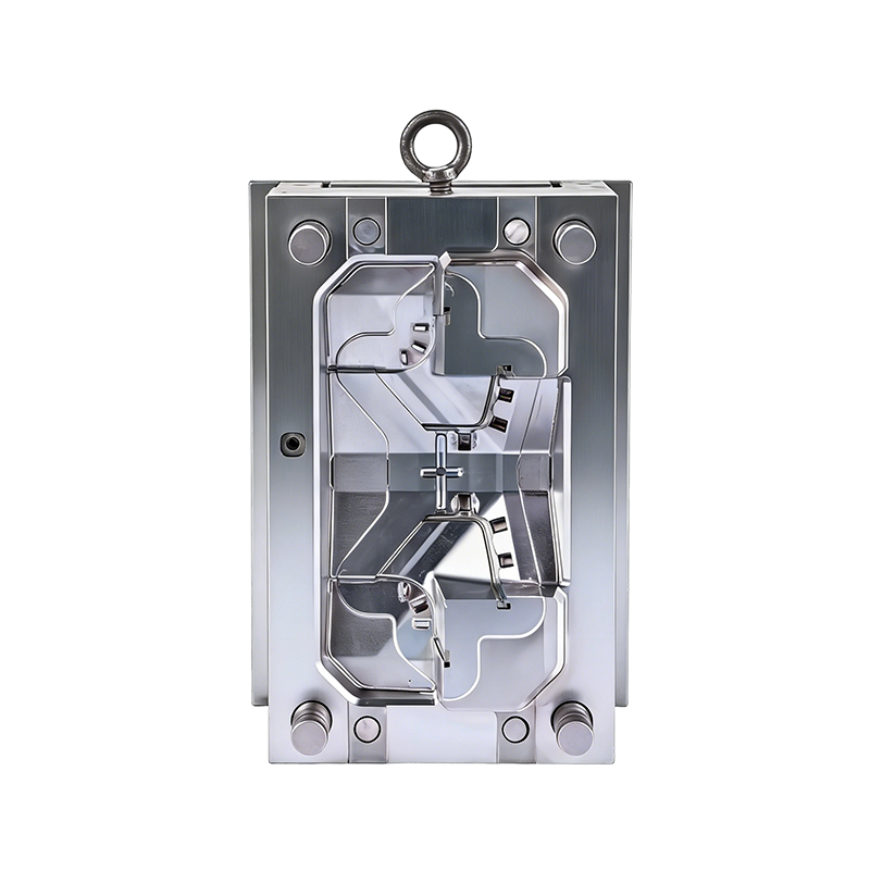
Stand next to any injection press running a part with side holes or external undercuts. You will notice something moving that is not the ejector plate. That movement comes from the driving mechanism for a plastic mold with slides. Slides exist because not every part feature aligns with the mold opening direction. A button hole on a power tool housing, a snap hook inside a medical device cover, or a thread on a bottle cap all require a core to pull sideways before the part can eject.
The angle pin as the primary driver
The most common driving mechanism uses nothing more than a steel pin cut at an angle. The angle pin mounts to the stationary half of the mold. The slide body rides on wear plates in the moving half. When the mold opens, the stationary half pulls away. The angle pin slides through a matching hole in the slide body, and because the pin is angled—typically between 15 and 25 degrees—it pushes the slide outward. No hydraulics, no cylinders, no sensors. Just geometry.
Supporting components that make it reliable
A simple angle pin works for small slides. For larger slides or heavier loads, mold designers add a locking wedge that seats against the back of the slide when the mold is fully closed. That wedge takes the injection pressure so the angle pin sees no load during fill. Spring-loaded return pins push the slide back inward on the closing stroke. Some high-cycle molds use hydraulic cylinders instead of angle pins. Hydraulics allow longer slide travel and independent timing, but they add complexity and leak risks.
A comparison from the shop floor
Mold A used angle pin actuation. Mold B used hydraulic cylinders. Mold A cost 15 percent less upfront and required no external hoses or valving. Mold B allowed each slide to retract 5 milliseconds earlier, shaving 0.8 seconds from the total cycle time. On a million-shot production run, Mold B produced 22,000 more parts per week.
What side-action means in practical terms
Walk through any high-volume injection molding plant, and you will hear the term side-action molds used interchangeably with slide molds. But there is a subtle difference. A slide typically refers to a mechanism built into the mold that moves at an angle to the parting line. A side-action usually means a core or cavity block that moves perpendicular to the mold opening direction—straight in and straight out, no compound angle.
The two main types of side-action actuation
Mechanical side-actions use the same angle pin principle as slides. The moving half pulls away, and the angle pin forces the side-action core outward. Mechanical systems are simple, reliable, and inexpensive. Their limitation is stroke length. An angle pin longer than about 80 millimeters becomes prone to bending, so mechanical side-actions work best for undercuts less than 25 millimeters deep.
Hydraulic side-actions use a cylinder mounted to the mold or the machine platen. Hydraulics provide consistent force regardless of stroke length. A hydraulic side-action can pull a core 100 millimeters or more. The trade-off is cost and maintenance. Hydraulic cylinders need seals that wear out, hoses that leak, and valves that stick.
How the timing sequence runs
A typical side-action cycle follows this pattern. Mold closes fully. A limit switch confirms the side-action core is in the forward position. Injection happens. After the cooling time, the mold begins to open. For mechanical side-actions, the angle pin engages immediately. For hydraulic side-actions, a timer or mold-open sensor triggers cylinder retraction. Once the core clears the undercut by a safe margin—usually one to two millimeters—the ejector plate advances and pushes the part off. On the closing stroke, the side-action returns to its forward position before the mold halves touch.
What Are the Material Selection Criteria and Optical Performance Considerations for Tail Lamp Assembly Molds?
Defining the dual mandate of structure and clarity
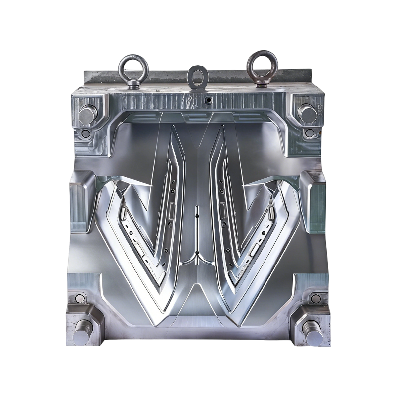
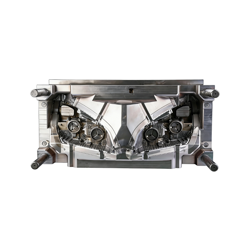
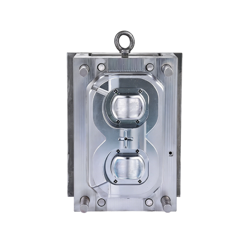
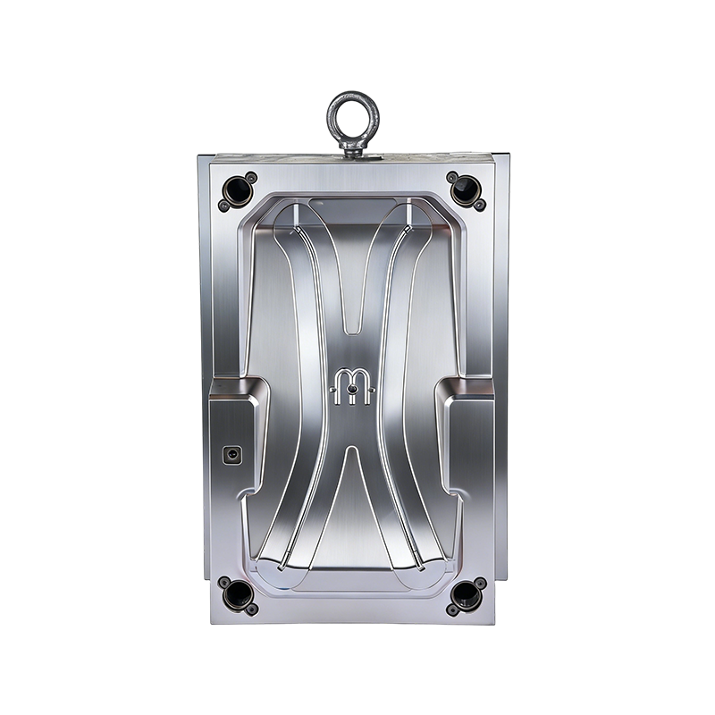
A Tail Lamp Assembly Mold faces a contradiction that few other automotive molds encounter. The same mold produces both the red outer lens—which must be optically clear and perfectly smooth—and the inner housing—which must be structurally rigid and heat-resistant. Material selection criteria for these two components pull in opposite directions.
Material requirements for the lens cavity
The lens is almost always molded from PMMA (acrylic) or PC (polycarbonate). Acrylic offers superior scratch resistance and weatherability. Polycarbonate offers better impact strength. Both demand a cavity surface polished to SPI-A1 with no visible scratches at 20x magnification. The mold steel must resist corrosion because both materials outgas under heat. Preferred grades include stainless steel like S136H or M340 hardened to 48–50 HRC.
Material requirements for the housing cavity
The housing sits behind the lens and holds the bulbs or LEDs. It must withstand under-hood temperatures and resist vibration. PBT-GF30 (glass-filled PBT) or ASA are common choices. Both contain abrasive fillers. The mold steel for the housing cavity needs wear resistance more than polishability. H13 or Stavax hardened to 50–52 HRC works well.
Optical performance requirements for the complete assembly
The table below summarizes the key optical criteria for tail lamp assembly molds and the failure modes when specifications are missed.
|
Optical Requirement
|
Target Value
|
How It Is Measured
|
Failure Mode If Missed
|
|
Lens clarity (haze)
|
Below 2%
|
ASTM D1003 haze meter
|
Cloudy appearance; failed ECE R148 or FMVSS 108
|
|
Light transmission
|
Above 90% for clear section, 25–45% for red section
|
Spectrophotometer with CIE illuminant A
|
Dark spots; uneven brightness across the lamp
|
|
Reflector surface roughness (housing)
|
Ra below 0.025 microns
|
White light interferometry
|
Scattered beam pattern; failed photometry test
|
|
Texture depth consistency (non-lens areas)
|
±1 micron from specified depth
|
Contact profilometer
|
Visible gloss variation after assembly
|
|
Material compatibility at weld lines
|
No visible haze or silver streaks after 500 thermal cycles
|
Thermal shock chamber followed by visual inspection
|
Weld line opens or discolors; customer field failure
|


 English
  عربى
عربى